
Sintered Titanium Mesh: The Structural Backbone of Modern Electrolyzer Stacks
In a PEM electrolyzer the porous titanium layer is the third-largest cost line in the stack, and the one whose failure takes the catalyst and the membrane down with it. This guide covers where sintered titanium mesh sits in the repeat unit, how the three manufacturing routes — powder-sintered plate, fibre felt and multilayer or expanded mesh — divide the structural and transport jobs, the parameters that belong on a drawing, and the failure modes that decide whether a stack reaches 60,000 hours.
Ask a stack designer to name the components that set electrolyzer performance and the porous transport layer rarely comes first. The membrane and the iridium catalyst get the attention, the bipolar plate gets the cost reviews. Yet the layer between them is doing four jobs at once — feeding water to the catalyst, clearing oxygen out of the structure, carrying current to the catalyst surface, and holding the membrane flat against a clamping load — and it is doing all four in an acidic, strongly oxidising, oxygen-saturated environment at 60–80 °C.
That combination is why carbon-based gas diffusion media, the default in fuel cells, does not survive here, and why sintered titanium has become the standard answer. It is also why the choice between powder-sintered plate, titanium fibre felt and sintered titanium mesh is not a material preference but a structural decision. The published titanium PTL design guide covers the parameter side of that decision; this article covers the mechanical side — what actually holds a stack together.
1. Where Sintered Titanium Mesh Sits in the Stack
A PEM electrolyzer stack is one repeat unit multiplied. From the end plate inward: end plate, bipolar plate, porous transport layer, membrane electrode assembly, porous transport layer, bipolar plate — repeated until the stack reaches its target output. The sintered titanium component occupies the porous transport layer on either side of the membrane, known in industry usage as the PTL.
Its position is fixed by stack geometry, so its requirements are imposed by the operating environment rather than by preference. On the anode side the layer is acidic, continuously wetted, continuously generating oxygen, and sitting at a potential that reaches and exceeds 1.8 V during oxygen evolution. Carbon paper oxidises to CO₂ under those conditions within hours to days; the practical rule used across the industry is that above roughly 1.6 V in an acidic environment, titanium is the only realistic substrate. The full material argument is laid out in titanium PTL vs carbon paper GDL.
Two consequences follow from that position, and both are expensive. The first is that the porous layer is the third-largest cost category in a stack by component group, behind the bipolar plate and the membrane electrode assembly — not because titanium is exotic, but because the area is large, the flatness tolerance is tight, and the surface often carries a precious-metal coating. The second is that its failure is never confined to itself. Coating degradation comes first, the membrane follows, and stack efficiency then declines across the whole unit. A component that costs a fraction of the MEA can shorten the MEA’s life.

Above: a titanium mesh-plate composite sintered diffusion layer — an expanded titanium mesh skeleton diffusion-bonded to a fine-pore sintered titanium plate. The mesh carries the clamping load; the plate sets the pore size the membrane and catalyst see.
This is the configuration most industrial stacks converge on once current density climbs past about 2 A/cm², because neither half does both jobs well enough on its own.
2. Three Routes to a Porous Titanium Layer
“Sintered titanium” is not a single product category. Three manufacturing routes dominate commercial supply, and all three can serve as a porous transport layer — but each is optimised for a different demand. Choosing by catalogue description rather than by function is the most common specification error in this part of the stack.
Powder-sintered plate is made from spherical or near-spherical pure titanium powder, pressed or rolled to shape and then sintered. Pore size is tight and uniform — typically 1–50 µm — the surface is flat, and compressive strength is high. It is the right choice when the pore tolerance itself is the specification. TOPTITECHS supplies this format as porous titanium plate for PEM PTL, including a 20 µm grade for PEMWE duty.
Titanium fibre felt is made from 20–50 µm titanium fibre laid in a nonwoven process and vacuum-sintered. Porosity runs high — 60–80% in standard grades, and up to 50–90% across the full range — with good three-dimensional connectivity, low resistance to fluid flow, and enough flexibility to conform to a flow field. The trade-off is flatness and compressive stiffness: a felt layer compresses under clamping load, which is measurable in contact resistance. The published sintered titanium fibre felt range covers the high-porosity end.
Multilayer sintered mesh and expanded mesh follow a different principle. Three to five woven titanium wire layers are stacked and sintered into a single body, or a single sheet of titanium is slit and stretched into a diamond expanded mesh. The design value here is not porosity but rigidity: the stacked or monolithic construction produces a three-dimensional through-pore network with high compressive strength. This is the format that suits the structural skeleton role in pressurised stacks. For the woven route see titanium woven mesh; the parameter interaction between porosity, thickness and pore size is quantified in how to choose a titanium PTL.
| Route | How it is made | Typical porosity | Strongest at | Weakest at |
|---|---|---|---|---|
| Powder-sintered plate | Spherical Ti powder pressed / rolled, then sintered | 30–50% | Pore tolerance control, flatness, compressive strength | Permeability; mass transport at high current density |
| Titanium fibre felt | 20–50 µm fibre laid nonwoven, vacuum-sintered | 60–80% (50–90% available) | Fluid transport, low flow resistance, conformability | Flatness and stiffness under clamp load |
| Multilayer sintered mesh | 3–5 woven layers stacked and sintered as one body | 30–60% (set by weave and wire diameter) | Dimensional stability, through-pore network, load bearing | Fine-pore precision; surface smoothness at the membrane |
| Expanded titanium mesh | Solid sheet slit and stretched into a diamond aperture | Set by strand width and aperture | Rigid single-sheet current collection, bubble release | Does not retain or distribute fine particles on its own |
3. Why Mesh Carries the Structural Load
The mechanical argument for mesh is easiest to see at the interface with the flow field. A bipolar plate presents alternating lands and channels. The porous layer bridges the gap between them, and under stack clamping pressure it deflects into the channel wherever it is unsupported. Deflection does three bad things at once: contact pressure becomes uneven across the active area, local contact resistance rises where the layer lifts off the land, and the membrane is pressed unevenly where the layer dips into the channel. Localised heating and localised membrane thinning follow.
The practical rule of thumb used in stack design is to keep the unsupported land-to-land span below roughly five times the PTL thickness. Below that ratio a 0.5 mm layer is comfortable over a 1–2 mm channel; a 0.25 mm research-grade felt is not, and needs a rigid substrate behind it. This is the constraint that pushes high-pressure stacks toward thicker, stiffer porous layers even though every extra 0.25 mm of sintered titanium adds measurable in-plane and through-plane resistance.
Sintered titanium mesh answers that constraint better than the alternatives because its stiffness comes from geometry rather than from density. A fibre felt reaches 60–80% porosity by accepting low compressive stiffness; a multilayer or expanded mesh reaches useful porosity while keeping a continuous metallic load path in the plane of the sheet. It also gives oxygen somewhere to go: the through-pore network is open in all three directions, so bubbles nucleating at the catalyst do not have to travel laterally to escape. Water management on the other side of the membrane is the mirror image of this problem and is covered in PEM fuel cell water management.
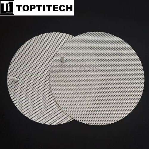
Above: 1 mm GR1 titanium expanded mesh, supplied as a rigid current collector and structural support for industrial PEM stacks. The diamond aperture is what makes it a conductor rather than a filter — current travels through continuous metal, gas travels through continuous void.
The same part is available with platinum or iridium oxide coating when the duty runs above roughly 2 A/cm².
4. The Composite Answer: Skeleton Plus Functional Layer
In practice the three routes are rarely used in isolation at industrial scale. Felt excels at fluid transport, powder plate at pore tolerance control, and mesh at maintaining dimensional stability under load — so stack designs increasingly combine them: mesh as the skeleton, felt or powder plate as the functional layer, sintered into one body rather than stacked loose.
Sintering the two together matters more than it appears. A loose stack of mesh plus felt has two contact interfaces, each with its own contact resistance and each capable of shifting under clamp load. A diffusion-bonded composite has one part, one thickness tolerance, and one predictable compression curve — which is what a stack assembler actually needs when torqueing a stack to a specified clamp pressure. The published titanium mesh-plate composite sintered diffusion layer is supplied in GR1 titanium at 100 × 100 × 2.0 mm, combining a 10 µm porous titanium plate with a 3 × 6 mm expanded mesh aperture.
Which face goes where is the decision to get right. The fine-pore side faces the membrane and the catalyst: it sets the local water distribution and supports the membrane against the pressure differential. The coarse mesh side faces the flow field: it distributes current, holds the composite flat against the lands, and gives oxygen a low-resistance escape path. Reversing the build is a common prototyping error and it shows up immediately as rising cell voltage at fixed current density.
5. Spec Sheet: What Goes on the Drawing
The parameters below are the ones that change stack behaviour. Values are the ranges normally quoted for PEM electrolyzer duty; where a fixed number appears it is the value on a published TOPTITECHS part, given so a drawing can be written against something real.
| Parameter | Typical range / published value | What it drives |
|---|---|---|
| Material and grade | GR1 (GR2 acceptable) | Corrosion resistance at the anode; GR1 is the default for maximum passivation stability — see titanium grades explained |
| Thickness | 0.25–2.0 mm; 0.5–0.8 mm typical for commercial stacks | Ohmic loss versus mechanical support; every extra 0.25 mm adds measurable resistance |
| Porosity | 55–75% is the functional window; felt to 60–80%, up to 90% on request | Below ~55% water transport limits the reaction; above ~80% the layer can imprint into the membrane |
| Average pore size | 5–50 µm; 10–30 µm recommended | Under ~10 µm oxygen bubbles blind the structure; over ~30 µm water floods through without distributing |
| Aperture (expanded mesh) | e.g. 3 × 6 mm diamond; strand set by sheet thickness | Bubble release and current collection, not filtration |
| Layer count (multilayer mesh) | 1–5 woven layers sintered as one body | Stiffness and through-pore connectivity |
| Flatness / thickness tolerance | Specify explicitly; drives clamp-pressure uniformity | Contact-resistance spread across the active area |
| Coating | Bare, Pt, or IrO₂ / Pt-Ir | Bare titanium passivates above ~1.6 V; specify coating above 2 A/cm² or beyond 40,000 h — see coated titanium PTL for high current |
| Maximum sheet size | Felt to 1600 × 600 mm; composite and plate to drawing | Active area per cell and number of parts per stack |
| Operating envelope | 60–80 °C (to 90 °C), atmospheric to 30 bar, 1–4 A/cm² commercial (to 6 A/cm²) | Coating stability, titanium passivation rate, mechanical load |
6. What Actually Kills a Titanium Mesh Layer
Most field failures in this component trace to one of six mechanisms, and all six are detectable in a specification review before a part is ever sintered.
Passivation. Bare titanium forms a thin oxide at anode potentials above roughly 1.6 V. The oxide protects the metal and slowly raises interfacial contact resistance at the same time, which shows up as cell voltage drifting upward at constant current. If the stack is specified above 2 A/cm² or targeted beyond 40,000 hours, the coating is not optional.
Coating defects. Coating thickness matters less than coverage uniformity. A pinhole in a platinum or IrO₂ layer becomes a local passivation site, and the resulting current redistribution accelerates degradation around it. Ask for adhesion and porosity checks on the coated surface, not just a loading figure in g/m².
Gas blinding and flooding. Two opposite errors with the same symptom. Pores below about 10 µm trap oxygen bubbles and block water flow; pores above about 30 µm let water pass through without distributing it across the catalyst. Both present as rising voltage and both are usually diagnosed late, because the part looks intact.
Mechanical imprint. Above roughly 80% porosity the solid–solid contact area shrinks, and under clamping pressure the layer can imprint into the membrane. The failure is irreversible and it is a stack-assembly problem as much as a material problem.
Fluoride attack. Titanium’s corrosion resistance comes from a passive TiO₂ film, and fluoride ions dissolve that film. Hydrofluoric acid, or fluoride-containing environments such as a degrading membrane releasing fluoride, is the one chemistry that takes titanium out of consideration. The boundaries are covered in sintered titanium filters for corrosive chemicals.
Differential pressure and thermal cycling. A 30 bar hydrogen output against an atmospheric oxygen side puts the porous layer in compression against the flow field on one face and against the membrane on the other. Repeated cycling works the contact interfaces; this is where a sintered composite outperforms a loose stack of layers.

Above: sintered titanium fibre felt at magnification. The open three-dimensional pore network is what makes felt the transport specialist — and the low solid fraction is exactly why it needs a mesh skeleton behind it under clamping load.
7. Beyond the Electrolyzer
The same sintered titanium structures earn their place well outside hydrogen service. The duties below share one characteristic: they defeat both stainless steel and polymeric media.
Corrosive media filtration
Liquid purification and catalyst recovery in nitric, sulphuric, acetic, oxalic and phosphoric acid, and in dilute hydrochloric acid. Corrosion rates for titanium in these media are substantially below those of stainless steel, which is why the corrosive-chemicals guide and the titanium sintered filter guide start from the same material argument as the electrolyzer anode.
Aeration and electro-oxidation
Biological aeration plates for wastewater treatment, micro- and nano-bubble diffusion, anode substrates for electrochemical oxidation, and electrolytic recovery of heavy metals. Here the valuable property is that titanium conducts in its own right: the part is electrode and distributor at once, so no organic binder and no separate current collector is needed. See platinized titanium mesh electrode and the DSA titanium anode range.
Pre-treatment and guard filtration
Profiled tube sections and guard filtration stages in seawater desalination plants. Titanium is close to inert against chloride, which makes it the established choice in seawater duty where 316L would pit.
Sterile filtration and high-purity water
Sterile liquid purification and high-purity water elements. A sintered body is monolithic — no loose particles, no extractables, and it survives steam sterilisation that would destroy a polymer element.
Plating bath filtration and anodes
Plating solution filtration and corrosion-resistant anode plates, where stable electrical resistance over the bath life matters more than the filtration rating itself.
8. Frequently Asked Questions
Is sintered titanium mesh the same thing as a titanium PTL?
A PTL — porous transport layer — is the function; sintered titanium mesh, fibre felt and powder-sintered plate are three routes to delivering it. When a drawing calls for a PTL without naming the route, the supplier has to guess between transport performance and structural rigidity, and those are different parts. Name the route, then the parameters. The decision tree is in titanium PTL design for PEM electrolyzers.
Why can’t I use carbon paper on the anode?
Oxygen evolution holds the anode above roughly 1.8 V in a strongly acidic, oxygen-saturated environment. Carbon is thermodynamically unstable there and oxidises to CO₂ within hours to days. Carbon paper belongs in fuel cells, not electrolyzers — the measured comparison is in titanium PTL vs carbon paper GDL.
Multilayer sintered mesh or titanium fibre felt for high current density?
Felt, for transport — at 3–4 A/cm² the limiting factor is getting water in and oxygen out, and felt’s 60–80% porosity wins. But pure felt compresses under clamp load, so above about 2 A/cm² the usual answer is a composite: felt or powder plate as the functional layer, mesh as the skeleton. If the stack is pressurised or the land-to-land span is wide, mesh moves from optional to required.
Does the mesh need a platinum or iridium coating?
Depends on the duty. Bare titanium passivates above roughly 1.6 V, and the oxide raises contact resistance over time. For continuous operation above 2 A/cm² or a life target beyond 40,000 hours, specify Pt or IrO₂. Below that — short-life test cells, low-voltage duty — bare titanium is a legitimate cost saving. See coated titanium PTL for high-current electrolysis.
Can mesh and felt be supplied as one sintered part?
Yes, and that is the recommended build for production stacks. A diffusion-bonded composite gives one thickness tolerance and one compression curve instead of two loose interfaces, each with its own contact resistance. A published example is the titanium mesh-plate composite sintered diffusion layer, GR1, 100 × 100 × 2.0 mm, 10 µm plate pore size over a 3 × 6 mm expanded mesh.
What sizes are available and how quickly can I get samples?
Titanium fibre felt is produced to 1600 × 600 mm in standard thicknesses from 0.25 mm to 4.0 mm, cut to sheet, disc or custom geometry. Composite and powder-plate parts are built to drawing. Sample parts in custom porosity, thickness and pore-size combinations typically ship within 7–10 days, which is fast enough to validate a combination before committing to production volume.
Does this work for AEM or alkaline electrolyzers?
The structural argument carries over unchanged; the material does not. In alkaline and AEM service nickel replaces titanium, and the equivalent porous layer is supplied as sintered nickel fibre felt for GDL and PTL. Everything in this article about thickness, porosity and flow-field span applies, but the corrosion boundary moves from fluoride to a different set of chemistries.
Specifying a porous titanium layer for a stack? Send your current density, cell pressure, active area, target pore size and clamp pressure to our applications team and we will come back with a recommended build — route, thickness, porosity and coating — plus sample lead time. Browse the Titanium PTL & Porous Plates and Metal Mesh categories for published specifications, or start from the titanium PTL for PEM electrolyzers product page.
References
- ASTM B265 – Standard Specification for Titanium and Titanium Alloy Strip, Sheet, and Plate.
- ASTM B348 – Standard Specification for Titanium and Titanium Alloy Bars and Billets.
- ASTM F316 – Standard Test Methods for Pore Size Characteristics of Membrane Filters by Bubble Point.
- ASTM G31 – Standard Guide for Laboratory Immersion Corrosion Testing of Metals.
- ASTM E8/E8M – Standard Test Methods for Tension Testing of Metallic Materials.
- ISO 22734 – Hydrogen generators using water electrolysis — Performance tests.
- U.S. Department of Energy, Hydrogen and Fuel Cell Technologies Office — published technical targets for PEM electrolysis (Hydrogen Shot).
- TOPTITECHS — Titanium PTL Design for PEM Electrolyzers: A Complete Engineering Guide (published on-site reference).
- TOPTITECHS — How to Choose a Titanium PTL: Porosity, Thickness & Pore Size (published on-site reference).
- TOPTITECHS — Titanium PTL vs Carbon Paper GDL (published on-site reference).